
In this feature, I am going to do a 360 degree mod on a micro servo motor for continuous rotation. I go through the modding step by step with clear pictures of the conversion process. Also, Python code will be included to drive the servo 360 degrees from the Raspberry Pi.
If I want a DC motor that can rotate 360 degrees continuously in both directions, I can use Micro Metal Gearmotors. After all, they are just as small and compact as the Micro Servo 9g. Furthermore, the metal gear motors have a metal shaft that makes it easy to attach other components.
However, if I only need to rotate something 360 degrees where rotational speed is not an issue, a modded micro servo can be an option to consider. Servos have an advantage where they can be connected directly to the microcontroller for control. So, unlike with the DC motors, no H-Bridge module is required. Furthermore, the micro servos are available from favourite stores at a much lower price than the Micro Gearmotors.
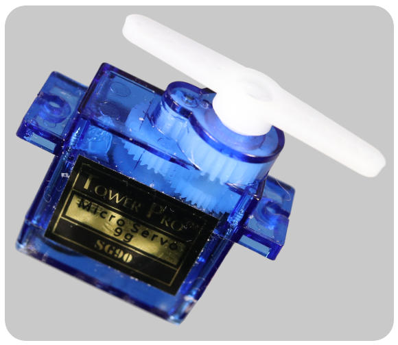
A review of the micro servo 9g with comprehensive specifications is available in a separate feature here.
360 Degree Servo Modding
DIFFICULTY
Successfully modding a servo for 360 degree rotation will depend on your skill and experience in performing similar delicate tasks. Even with experience, the modding can fail to some degree, even if it is down to losing a component such as a gear or a screw. So, plan for failure by purchasing a batch of micro servos, especially if going for the cheapest available.
HAZARDS
- You will have to take care when applying the Super Glue. Because not only is it a hazard in itself, if you misapply the glue, there is no easy undo button.
- It is possible to mod the servo to 360 degree rotation without using power tools. However, some drilling and cutting are necessary, so make use of personal protection gear where appropriate.
TOOLS
- You will drill one component, but this can be done using a hand tool that can hold a 1.5 mm sharp drill bit.
- A very sharp knife to cut off a plastic notch on a gear.
- To fit the tiny screw heads, you will require precision type slot or POZI screwdriver.
- Since this is a website for programmable robot projects instead of RC related stuff, I will be using an Arduino type board and some code to centre the servo potentiometer. However, a servo tester will work if you have one.
CONSUMABLES
- I’m using Loctite Super Glue that has a Precision extra long nozzle. I will be using super glue to lockdown the servo potentiometer.
The 360 Degree modding Process
TAKING APART
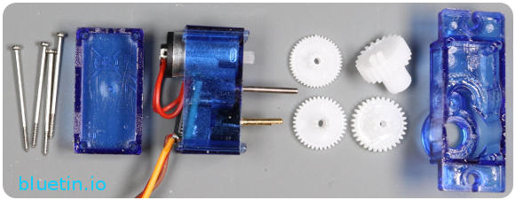
Using a precision screwdriver, remove the four screws from the rear of the servo body. Then pull the casing apart to reveal the plastic gears. Next, put the screws in a safe place, then, remove all the gears from the shafts. Some light force will be necessary to remove the gears from the Potentiometer shaft (Horn axel).
ARDUINO SETUP
// sketch to set servo centre postion
#include <Servo.h>
// create servo object to control a servo
Servo myservo;
// variable to store the servo position
int pos = 90;

void setup() {
  myservo.attach(9);  // attaches the servo on pin 9 to the servo object
}

void loop() {
    // tell servo to go to position in variable 'pos'
    myservo.write(pos);
    // waits 15ms for the servo to reach the position
    delay(15);
}
Optionally set up an Arduino type board to centre the servo potentiometer. Use the code above as an example, but be sure that the servo centre value is correct.
SET & GLUE SERVO POTENTIOMETER
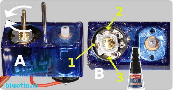
You will be using either an Arduino or another kind of servo tester to help centre the potentiometer. So this will be an excellent time to connect the servo and power up the tester of choice. If the servo potentiometer is not in a neutral position, the servo motor may start to turn after power up. Rotate the potentiometer shaft (A) with either fingers or needle pliers until the servo motor stops rotating.
If you check at point 1 in the image above you can see an indication to confirm a neutral position. So if the mechanical feature of the potentiometer looks out of ‘obvious’ alignment, it will be worth checking the Arduino code to make sure a 90-degree value (middle position) is correctly set.
APPLYING GLUE
Once you are sure the servo potentiometer is in a neutral position and the servo motor is no longer rotating, disconnect the servo from the tester. Next, without disturbing the potentiometer, apply the super glue at points 1, 2, 3 using the above image as the reference. Then, give plenty of time to allow the glue to set; the length of a long coffee break will be enough to be sure.
Enable 360 Degree Rotation
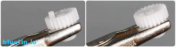
To enable 360 degree continuous rotation the notch has to be cut off the horn gear. You can remove the notch easily by using a sharp hobby knife.
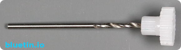
Next, we require a round hole through the same servo gear to allow it to rotate freely around the potentiometer shaft. In my case, a sharp 1.5 mm drill bit will do the job. The drill bit will go part way into one end of the gear, using at least a hand drill, drill the hole the rest of the way. That is the 360 degree servo mod done.
ASSEMBLING THE MICRO SERVO
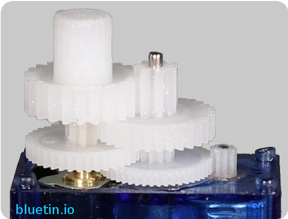
While using the image above as a reference, the gears can now be put back on the shafts. Make sure that the modified gear can rotate freely on the shaft before completing the assembly.
Next, assemble the servo case parts and secure with the screws, but do not to over tighten.
Testing 360 degree rotation
It is not the smoothest servo rotation I have seen, and that might be due to the initial quality of the servo. It is also possible that the potentiometer might not be giving consistent feedback. Furthermore, despite glueing the potentiometer in a neutral position, some trimming in code might be necessary to find a new stop position.
ARDUINO 360 DEGREE ROTATION SERVO TEST
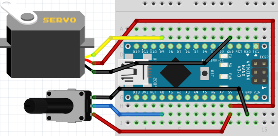
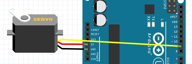
Using the above circuit, load the Knob sketch from the Arduino IDE Examples>Servo>Knob. This sketch, while turning the potentiometer, will rotate the servo 360 degrees in either direction. Use this sketch to do a first test of the servo modification.
Raspberry Pi 360 DEGREE SERVO ROTATION TEST
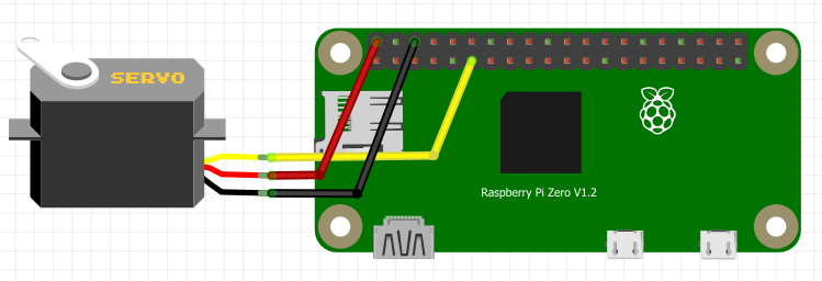
The 360 degree continuous rotation micro servo is tested on the Raspberry Pi Zero W with the Servo signal wire (Yellow/Orange) connected to GPIO17 (Pin 11). The red and black/brown wire of the servo is connected to 5v and ground on the Raspberry Pi respectively.
#!/usr/bin/env python3

"""
servo_test_360.py
www.bluetin.io
17/01/2018
"""

__author__ = "Mark Heywood"
__version__ = "0.01"
__license__ = "MIT"

from gpiozero import Servo
from time import sleep

# Adjust the pulse values to set rotation range
min_pulse = 0.000544	# Library default = 1/1000
max_pulse = 0.0024		# Library default = 2/1000
# Initial servo position
pos = 0
test = 0

servo = Servo(17, pos, min_pulse, max_pulse, 20/1000, None)

def delays(pos):
	if pos == 0:
		print('Stop', pos)
		sleep(3)
	elif pos == 1.0:
		print('Full Left', pos)
		sleep(3)
	elif pos == -1.0:
		print('Full Right', pos)
		sleep(3)
	else:
		print(pos)
		sleep(1)

while True:
	# For statement example
	for pos in range(0, 20):
		pos = pos * 0.1 - 1
		servo.value = pos
		delays(pos)

	for pos in range(20, -1, -1):
		pos = pos * 0.1 - 1
		servo.value = pos
		delays(pos)
With the servo connected to the Raspberry Pi, the above Python code rotates the servo 360 degrees in a sweeping fashion. Additionally, there are delays set so that the servo will sustain a position for a period. For instance, when the servo reaches the stop position, a delay is executed to hold that position for a period.
Experiment with the above Python code to test the behaviour of the servo under different programming conditions.
References
- Pololu Micro Metal Gearmotors – Link.
- TowerPro Micro Servo 9g – Link.
- Circuit connection diagrams in this feature made with Fritzing App – Link.
Related Articles

Micro Servo 9g – Raspberry Pi Servo Motor Python Code Test – Link.

Raspberry Pi Headless Install Without A Display Guide – Link.
Buying Featured Items
The purchase price is going to vary greatly depending on how quickly you want the items. Therefore shop around checking out Amazon, Ebay, Adafruit and local electronic stores.
UK Searches:
UK Amazon:
- Micro Servo – Search
- Arduino – Search
- Raspberry Pi – Search
- MicroSD Card – Search
- Raspberry Pi Compatible Wi-Fi Dongle – Search
US Searches:
US Amazon:
- Micro Servo – Search
- Arduino – Search
- Raspberry Pi – Search
- MicroSD Card – Search
- Raspberry Pi Compatible Wi-Fi Dongle – Search
On Closing
I hope you find this article useful – 360 Degree Mod for Servo Continuous Rotation – Guide, please like and share.
One thought on “360 Degree Mod for Servo Continuous Rotation – Guide”
Comments are closed.