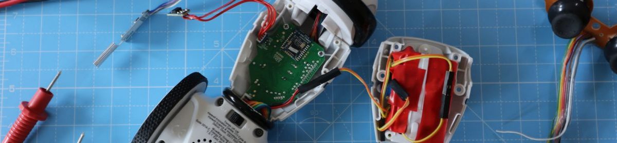
In this article, we look at how to access an Arduino port to read or manipulate a group of pins in C code. We use bitwise operators to read, set and invert bits in variables and device registers. To help with this feature, we will use a simple robot controller to demonstrate how we might use port manipulation. I include, for example, Arduino test code and illustrations of bitwise operations.
Bitwise operators are handy if you want to manipulate bits within a variable or Arduino memory registers. However, with bitwise operations, we can also share variables or microcontroller registers with other programming operations by discriminating bits with a mask. For example, in this feature, we demonstrate how to manipulate an Arduino pin register that has serial port pins we don’t want to disturb. So, while the Arduino port D is 8-bits wide, our simple robot controller will only use 6 of these bits. Using a port mask will help us avoid using the remaining two bits that the serial port module uses.
Simple Robot Controller using Arduino Port D
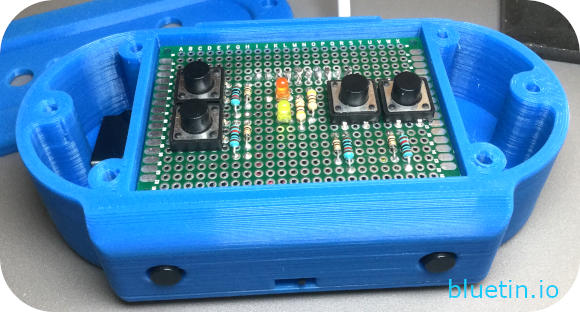
To create the Arduino simple robot controller, I solder six tactile type switches to prototyping PCBs. I arrange four of the switches to provide steering and drive control for robot manoeuvres. Additionally, I add two more switches to allow operation of other features of the robot. These two switches are in the trigger position of the controller, and I solder them to a separate PCB from the other four switches.
Fortunately, while this feature is not a controller build walkthrough, the PCB circuit is easy enough to create from the schematic below.
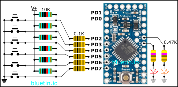
The circuit above shows how we connect the switches to the Arduino port D.
I connect six switches to the Arduino port D while leaving pins PD0 and PD1 free for serial module connections. Furthermore, I add two L.E.D.s to the circuit to help with program status indications and debugging during controller operation. However, to avoid dazzling the controller operator, I select higher value resistors to dim overly bright L.E.D.s.
Aside from the switches, to make the circuit complete, I include pull-up resistors to set the initial switch state. And, to guard against unintended pin configurations, I also include current limiting resistors to the circuit for some protection.
Arduino Port Bitwise Operations
Here, we are going to look at some illustrations of bitwise operations that are mostly related to the example code below. We will be referring to port D because this is the port we are using on the Arduino board. However, I’ll sometimes refer to the Arduino memory registers as DDRx, PORTx and PINx when not referring to a specific port. Otherwise, I’ll call the registers as DDRD, PORTD and PIND when referring to port D specifically.
Arduino Port DDRx Register
Configuring the data direction register (DDRx)of the Arduino port is usually the first step to preparing the Arduino board pins for use. We use this register to set the pins to either input or output. So if we are going to use our code to read the state of the switches on the robot controller, we will set the pins to input.
However, we are only going to use the six most significant bits of the DDRx register. The two least significant bits set data direction for the serial module. But, we want to avoid upsetting the serial module configuration. So, by using a mask and bitwise operators, we can choose which bits to manipulate.
Arduino Port Manipulation Illustrations
SET PINS 7 – 2 AS INPUTS
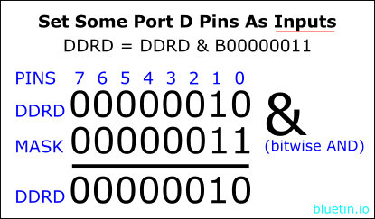
The Arduino ATmega type microcontrollers by default have the pins set to inputs I believe. So, we could skip the pin configuration as shown in the illustration above since the data direction register does not change. However, if there is a serial module configuration, using the mask will preserve that configuration.
To configure an Arduino pin as an input, we write a digital 0 to the corresponding bit in the mask. However, any bit sate we want to keep in the register, we will write a digital 1 to the same bit position the mask.
When manipulating the port register, using the bitwise AND operator and mask you can:
- Clear existing set bits.
- Preserve existing set and unset bits.
- Check the state of a bit.
SET PINS 7 – 2 AS OUTPUTS
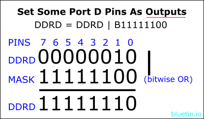
However, if you want to configure the Arduino port D pins as outputs, you will have to use the bitwise OR operator. Again, we continue to manipulate only the six most significant bits. So we don’t want to change the serial port pin configuration as before.
We do not need to care about the contents of the DDRx register. Our mask will set any DDRx bit where we have set a bit in the mask. So to configure a pin for data output, we will set the corresponding bit to a digital 1 in the mask. However, writing a digital 0 to a bit in the mask will not affect the corresponding bit in the DDRx register.
When manipulating the port register, using the bitwise OR operator and mask you can:
- Set bits.
- Preserve existing bits.
Arduino Port PORTx Register
We write to the PORTx register to set the Arduino port pins to either a HIGH state or a LOW state. You can set the data direction register (DDRx) to either input or output for PORTx register manipulation. Furthermore, like the DDRx register, the PORTx register is also readable and writable. So, the bitwise operations we apply to the DDRx register above will also work on the PORTx register.
// LED swtching
void activityLED(boolean newState) {
  if (newState == true) {
    // Turn on activity LED on pin A3
    PORTC = PORTC | B00001000;
  } else {
    // Turn off activity LED on pin A3
    PORTC = PORTC & B11110111;
  }
}
The above code snippet, from the example Arduino program below, controls an L.E.D. on PORTC pin 3. So, here I’m using bitwise operations instead of using the digitalWrite() function to control the L.E.D.
You can use bitwise manipulation on the PORTx register for cases like the following:
- Driving an H-Bridge module like the L298N module and the TB6612FNG module for DC motor control.
- Control an array of L.E.D.s that you connect to pins on the same Arduino PORTx.
- Efficiently operate stepper motor driver boards by connecting the driver control pins to the same microcontroller PORTx.
Arduino Port PINx Register
Our Arduino code is reading signals from the switch presses on the simple robot controller. So, to read those switch signals, our code will read the PINx register on the microcontroller device memory. But, note that the PINx is a read-only register. As above, we will only process the six most significant bits.
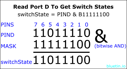
We are using pull-up resistors on our switch circuit which will pull the switch signals high. This high signal will remain until an associated switch is pressed. Therefore, by pressing a switch, the connecting signal line will be pulled low making the pin state digital 0 instead of 1. Then, we can get this pin state by reading the PINx register. For example, if you look at PIND in the illustration above, you can see that a switch has pulled bit-5 low.
Ideally, we want to take a snapshot of the switch states on the Arduino port D. This snapshot will keep the data consistent until we finish processing it. Therefore, when applying a bitwise operation on PIND, we put the result in a new variable called switchState.
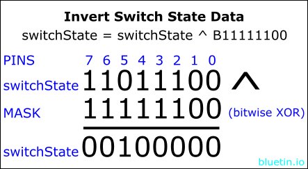
The illustration above shows an extra step we can take so that any switches we press, show as a digital 1. Using the bitwise XOR operator will allow us to flip the bits while using a mask for bit selection.
Reading the PIND register on Arduino Port D
However, if you want to read the switch pin without further processing, see the following code snippet:
const uint8_t RT = B00100000; // bit-5, Right Turn

if ((PIND & RT) != RT) {
  // Switch press on bit-5
}
We create a switch constant showing bit-5 as our switch position. We then use this constant against the PIND register to detect a switch press on the Arduino port D pin 5.
const uint8_t RB = B10000000; // bit-7, Right bumper
const uint8_t LB = B01000000; // bit-6, Left bumper
const uint8_t RT = B00100000; // bit-5, Right Turn

while(1) {
  // Copy bits of interest using a mask.
  switchState = PIND & B11111100; // bitwise and

  if ((switchState & RB) != RB) {
    // Switch press on bit-7
  }
  if ((switchState & LB) != LB) {
    // Switch press on bit-6
  }
  if ((switchState & RT) != RT) {
  // Switch press on bit-5
  }
}
However, if you want to check an array of switches, run multiple if statements against a temporary snapshot of the PIND register instead. Furthermore, you can use separate ‘if ‘ statements to check for multiple switch presses per cycle.
Example Code For Manipulating Arduino Port D and C
The code below is a full working example of reading switches attached to an Arduino port. First, Wire the circuit as above, load the program, then view the output on the serial monitor. As well as the binary data output, by setting the debug flag to true, you can view a more descriptive output.
/* simple_robot_controller.ino
 *
 * Simple Robot Controller
 * Version 0.01
 *
# MIT License
#
# Copyright (c) 2018 Mark A Heywood
# Author: Mark A Heywood
# https://www.bluetin.io/
#
# Permission is hereby granted, free of charge, to any person obtaining a copy
# of this software and associated documentation files (the "Software"), to deal
# in the Software without restriction, including without limitation the rights
# to use, copy, modify, merge, publish, distribute, sublicense, and/or sell
# copies of the Software, and to permit persons to whom the Software is
# furnished to do so, subject to the following conditions:
#
# The above copyright notice and this permission notice shall be included in
# all copies or substantial portions of the Software.
#
# THE SOFTWARE IS PROVIDED "AS IS", WITHOUT WARRANTY OF ANY KIND, EXPRESS OR
# IMPLIED, INCLUDING BUT NOT LIMITED TO THE WARRANTIES OF MERCHANTABILITY,
# FITNESS FOR A PARTICULAR PURPOSE AND NONINFRINGEMENT. IN NO EVENT SHALL THE
# AUTHORS OR COPYRIGHT HOLDERS BE LIABLE FOR ANY CLAIM, DAMAGES OR OTHER
# LIABILITY, WHETHER IN AN ACTION OF CONTRACT, TORT OR OTHERWISE, ARISING FROM,
# OUT OF OR IN CONNECTION WITH THE SOFTWARE OR THE USE OR OTHER DEALINGS IN
# THE SOFTWARE.
*/

// Debug flag
boolean buttonDebug = false;

// Initialise controller switch constants for port D
const uint8_t RB = B10000000; // Right bumper
const uint8_t LB = B01000000; // Left bumper
const uint8_t RT = B00100000; // Right turn
const uint8_t LT = B00010000; // Left turn
const uint8_t FD = B00001000; // Forward direction
const uint8_t RD = B00000100; // Reverse direction

// LED on/off flags
const boolean onLED = true;
const boolean offLED = false;

// Initialise global variables
uint8_t lastSwitchState = 0;


// LED swtching
void activityLED(boolean newState) {
  if (newState == true) {
    // Turn on activity LED
    PORTC = PORTC | B00001000;
  } else {
    // Turn off activity LED
    PORTC = PORTC & B11110111;
  }
}


void setup() {
  Serial.begin(9600);
  /*
   * Set pins to output on port C for the activity LED
   * and status LED.
   */
  DDRC = DDRC | B00001100;
  // Turn on the LEDs above for initial startup test.
  PORTC = PORTC | B00001100;

  /* Set pins to input on port D to read switches
     while preserving the current serial port pins. */
  DDRD = DDRD & B00000011;
  // A short pause before begining the main program.
  delay(1000);
}


void loop() {
  uint8_t switchState = 0;
  char* debugMessage[10];

  while(1) {
    // Copy bits of interest using a mask.
    switchState = PIND & B11111100; // bitwise and
    // Invert bits of interest using the same mask.
    switchState = switchState ^ B11111100;  // bitwise xor

    if (switchState & LB) {
      activityLED(onLED);
      *debugMessage = "LB, bit 6";
    } else if (switchState & RB) {
      activityLED(onLED);
      *debugMessage = "RB, bit 7";
    } else if (switchState & LT) {
      activityLED(onLED);
      *debugMessage = "LT, bit 4";
    } else if (switchState & RT) {
      activityLED(onLED);
      *debugMessage = "RT, bit 5";
    } else if (switchState & FD) {
      activityLED(onLED);
      *debugMessage = "FD, bit 3";
    } else if (switchState & RD) {
      activityLED(onLED);
      *debugMessage = "RD, bit 2";
    } else {
      activityLED(offLED);
      *debugMessage = "Idle.....";
    }

    if (buttonDebug) {
      if (switchState != lastSwitchState) {
        lastSwitchState = switchState;
        Serial.println(*debugMessage);
      }
      Serial.print("Switch State: ");
      Serial.println(switchState);
      delay(100);
    }

    if (!buttonDebug) {
      if (switchState) {
        Serial.write(switchState);
        delay(5);
      }
    }
  }
}
Arduino Port Manipulation – What Next?
The above example code is enough to send control commands to an onboard robot controller. Also, in addition to the above circuit, adding a Bluetooth module will provide an easy wireless control solution.
The next challenge will be to create an onboard robot controller that will use Arduino port manipulation to drive an H-Bridge module.
SHOPPING
DISCLAIMER: This feature may contain affiliate links, which means that if you click on one of the product links, I’ll receive a small commission. This commission helps support the website and allows me to continue to make features like this. Thank you for the support!
Banggood
Banggood provides faster shipping than ebay.
- 40pcs FR-4 2.54mm Double Side Prototype PCB Printed Circuit Board – Link.
-
20Pcs Tactile Push Button Switch Momentary Tact Caps – Link.
REFERENCES
- Arduino Language Reference – Port Registers – Link.
- Arduino Language Reference – Bitwise Operators – Link.
RELATED ARTICLES

Robot Control with Raspberry Pi and Python – Link.
On Closing
I hope you find this article useful – Arduino Port Access & Bitwise Op. using Simple Robot Controller, please like and share.