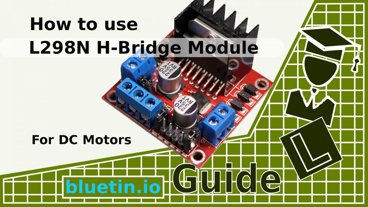
If you are looking to build your own robot vehicle, you may consider using DC Motor H-Bridge Modules. So this quick how-to guide will help you get going quickly with the L298N Dual H-Bridge DC Motor Driver Module. Included, is an easy wiring connection diagram and some start code for quick reference.
L298N H-Bridge Module Overview
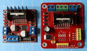
The L298N Module is large in size and will need plenty of space if fitting inside a vehicle. However, with the size of motor that this can support, you can have a vehicle large enough to support its physical size.
You can consider using the L298N H-Bridge Module for driving DC motors that are typically installed in custom built robots or vehicles. For the DC motors that are found in a child’s RC toy vehicle, the L298N H-Bridge Module can be a bit overkill. So you might want to consider the TB6612FNG instead; which is also great for the Micro Metal Gear Motors – Link to guide.
DC motors typically do not need an H-Bridge driver to operate. For it is only necessary when you need to change the rotation direction of the motor spin. Therefore, a transistor or MOSFET circuit will only be necessary to drive a DC motor if driving the motor spin in only one direction.
Some L298N Specifications
- Double H-Bridge Drive
- Chip: L298N
- Logical Voltage: 5V
- Drive Voltage: 5V-35V
- Logical Current: 0mA-36mA
- Drive Current: 2A (Max Single Bridge)
- Max Power: 25W
- Size: 43 x 43 x 27mm / 1.7 x 1.7 x 1 inch
- Weight: 30g / 1oz
Powering The L298N Module
In most situations, the H-Bridge Module is likely to be powered by battery where the voltage is likely to drop over time. Therefore it is necessary to consider what is the maximum and lowest voltage you need for good system operation. Knowing this will help you decide when you need to disable the H-Bridge 5v regulator.
Furthermore, in the case of dc motor battery supply voltage, it is not always convenient to try to perfectly match battery supply voltage to ‘nominal’ dc motor voltage. Also, in the case of the L298N H-Bridge Module, there will be about 1.4v voltage drop between the battery and dc motor. In addition, you will need to consider the difference between the battery nominal voltage and the fully charged battery voltage.
Consequently, when matching dc motors to various battery types and battery voltages, your dc motors in some cases are going to be slightly under or overpowered.
Different L298N H-Bridge Set-ups
12v DC Motor Supply (recommended):
- Connect the 12v dc motor power supply to the H-Bridge module.
- Enable the onboard 5v dc regulator by shorting the jumper pin.
- Connect 12v dc motors to the H-Bridge module.
- You can power your Arduino from the onboard 5v dc regulator.
24v DC Motor Supply:
- Connect the 24v dc motor power supply to the H-Bridge module.
- Disable the onboard 5v dc regulator by opening the jumper pin.
- Connect 24v dc motors to the H-Bridge module.
- Use a separate power supply for your Arduino, and common the power ground rails. Otherwise, connect a dc-dc step-down converter to the motor power supply to power your micro-controller.
- Connect a 5v power source to the H-Bridge driver module; it can be the same power source in point 4 above.
6v DC Motor Supply:
- Connect 6v dc motor power supply to the H-Bridge module.
- Disable the onboard 5v dc regulator by opening the jumper pin.
- Connect 3v-6v dc motors to the H-Bridge module.
- Use a separate power supply for your Arduino, and common the power ground rails. Otherwise, connect a dc-dc Constant Voltage Step Up Down converter to the motor power supply to power your micro-controller.
- Connect a 5v power source to the H-Bridge driver module; can be the same power source in point 4 above.
L298N Power Solution Example
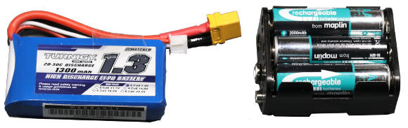
If you are using high power 6-volt dc motors, you may be looking to use a 2S (7.4V) RC LiPo battery or six 1.2V rechargeable batteries. However, in this case, the nominal battery voltage will not be enough to power the L298N module onboard 5V regulator. So, we will need an alternative 5V power source to power the H-Bridge module.
We may want to discharge the battery packs to as low as 6 volts before returning the batteries to the charger. That means there is little headroom to support dropout voltages from 5V regulators. One of the ways to avoid these dropout voltage issues or even battery voltage dips, we can use a buck-boost DC to DC converter in our motor driver circuit.
L298N & BUCK-BOOST DC CONVERTER USAGE EXAMPLE
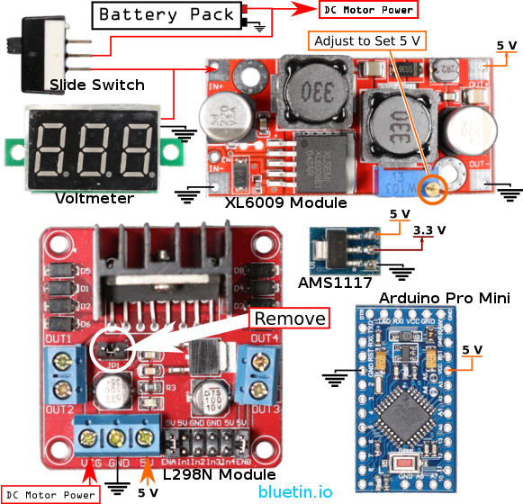
The Buck-Boost module I am using here (also step-up, step-down converter) is an XL6009 module. This module is typical of what you will find on Ebay or Banggood shopping websites. Pololu however, has a much better range of DC to DC converters with much better specifications in more compact sizes. But for experimental purposes and if space allows, the XL6009 module will work. And this module will provide logic level power to the L298N and other 5V logic connections.
Avoid Accidental Battery Discharge
I am currently using the XL6009 in Arduino and Raspberry Pi robotic applications without issues. However, one thing to note though, these modules can draw current from the battery even when the module is not powering anything else. So, when the robot project is not in use, someway to isolate the battery is necessary to avoid accidentally over discharging batteries.
Adding a voltage feedback display will help avoid over-discharging batteries during use. An inexpensive mini L.E.D digital voltmeter module can be a quick add-on for good visible feedback.
Connecting The L298N H-Bridge Module
The L298N module supports up to two motors. So you will need three output pins on the Arduino micro-controller for each motor. Additionally, if you want motor speed control, one of the three Arduino pins should ideally be a hardware PWM pin.
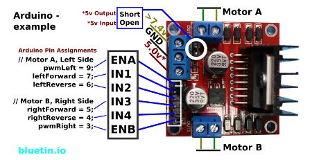
The following Image illustrates how an Arduino micro-controller can be connected to the H-Bridge module.
Arduino Connection Start Code
The code below shows an example of how the wire connections have been assigned. You have the pin declarations that connect to the L298N module, and you also have the Arduino initialisation for each pin.
///////////////// Define Pins /////////////////

// Motor A, Left Side
const uint8_t pwmLeft = 9;      // ENA - Enable and PWM
const uint8_t leftForward = 7;  // IN1 - Forward Drive
const uint8_t leftReverse = 6;  // IN2 - Reverse Drive

// Motor B, Right Side
const uint8_t pwmRight = 3;     // ENB - Enable and PWM
const uint8_t rightForward = 5; // IN3 - Forward Drive
const uint8_t rightReverse = 4; // IN4 - Reverse Drive

//////////////// Start Functions //////////////////

// All Stop
void allStop() {
  digitalWrite(leftForward, LOW);
  digitalWrite(leftReverse, LOW);
  digitalWrite(rightForward, LOW);
  digitalWrite(rightReverse, LOW);
  analogWrite(pwmLeft, 0);
  analogWrite(pwmRight, 0);
}

void allForward() {
  digitalWrite(leftForward, HIGH);
  digitalWrite(leftReverse, LOW);
  digitalWrite(rightForward, HIGH);
  digitalWrite(rightReverse, LOW);
  analogWrite(pwmLeft, 255);
  analogWrite(pwmRight, 255);
}

void allReverse() {
  digitalWrite(leftForward, LOW);
  digitalWrite(leftReverse, HIGH);
  digitalWrite(rightForward, LOW);
  digitalWrite(rightReverse, HIGH);
  analogWrite(pwmLeft, 255);
  analogWrite(pwmRight, 255);
}

void skidsteerLeft() {
  digitalWrite(leftForward, LOW);
  digitalWrite(leftReverse, HIGH);
  digitalWrite(rightForward, HIGH);
  digitalWrite(rightReverse, LOW);
  analogWrite(pwmLeft, 255);
  analogWrite(pwmRight, 255);
}

void skidsteerRight() {
  digitalWrite(leftForward, HIGH);
  digitalWrite(leftReverse, LOW);
  digitalWrite(rightForward, LOW);
  digitalWrite(rightReverse, HIGH);
  analogWrite(pwmLeft, 255);
  analogWrite(pwmRight, 255);
}

//////////////// End Functions //////////////////

void setup() {
  // Set pins to motor driver (L298) to outputs
  pinMode(pwmLeft, OUTPUT);
  pinMode(leftForward, OUTPUT);
  pinMode(leftReverse, OUTPUT);
  pinMode(pwmRight, OUTPUT);
  pinMode(rightForward, OUTPUT);
  pinMode(rightReverse, OUTPUT);
}

void loop() {
  allStop();  // Stop all dc motors
  delay(1000);
  allForward(); // Drive dc motors forward
  delay(2000);
  allReverse(); // Drive dc motors in reverse
  delay(2000);
  skidsteerLeft();  // Skidsteer spin left direction
  delay(2000);
  skidsteerRight(); // Skidsteer spin right direction
  delay(2000);
}
Related Articles

GPIO PWM For Raspberry Pi H-Bridge DC Motor Control – Link.
TB6612FNG Dual DC Motor Driver and Arduino Circuit guide – Link.
Buying Featured Items
The purchase price is going to vary greatly depending on how quickly you want the items. Therefore shop around checking out Amazon, Ebay, Adafruit and local electronic stores.
DISCLAIMER: This feature may contain affiliate links, which means that if you click on one of the product links, I’ll receive a small commission. This helps support the website and allows me to continue to make features like this. Thank you for the support!
BANGGOOD
Although you will find the same items on Ebay, Banggood has faster shipping options when ordering items from China.
- DC-DC Boost Buck Adjustable Step Up Step Down Converter XL6009 Module – Link.
- L298N Dual H Bridge Stepper Motor Driver Board – Link.
- 0.28 Inch 2.5V-30V Mini Digital Volt Meter – Link.
- Arduino compatible Pro Mini 5 volts – Link.
- PCB Panel Mini Vertical Slide Switch – Link.
- 40pcs FR-4 2.54mm Double Sided Prototype PCB – Link.
On Closing
I hope you enjoy using the L298N Dual H-Bridge Module. Also, I hope you’ll be returning to this site in the future for more robotics projects and guides.
2 thoughts on “L298N H-Bridge DC Motor Driver Module Quick Start Guide”
Comments are closed.