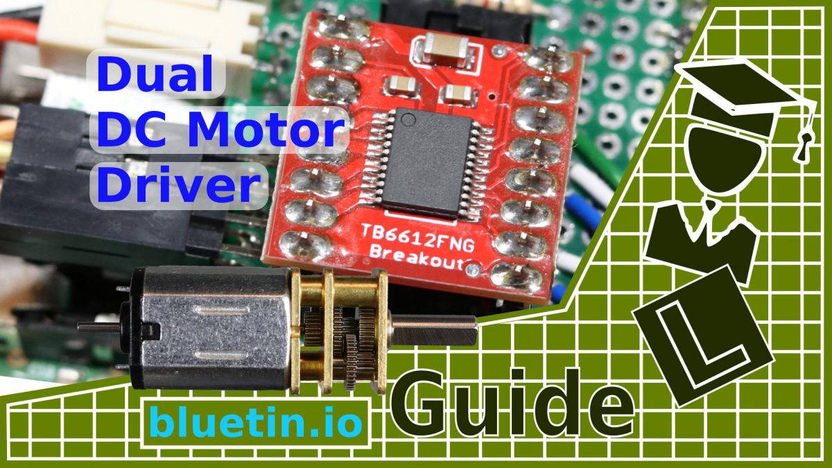
The TB6612FNG Dual H-bridge DC motor driver is ideal for small robot vehicles using the Micro Metal Gearmotors. This guide looks at how to use this driver when connected to Arduino compatible boards using single power supply options. Therefore, review this guide for pinouts and example circuit diagrams for 3.3 Volts and 5 Volts.
Welcome to the TB6612FNG Motor Driver. This breadboard friendly driver board will fit inside some of the smallest robots available, especially when connecting wires are soldered directly to the pads. So, if you use this motor driver with an Arduino Pro Mini and an NRF24L01 wireless module, you have a very powerful compact module for a programmable, wireless control robot. If you are also interested in Raspberry Pi robot vehicles, view the following post for attaching this motor driver to a Raspberry Pi:
Motor Driver for Raspberry Pi Robot using TB6612FNG – Link.
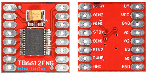
TB6612FNG Motor Driver
Specifications
- Motor supply voltage 2.5 V to 13.5 V.
- Supply voltage (VCC): 2.7 V to 5.5 V
- Output current: 1.2 A average and 3.2 A peak.
- Function modes: CW, CCW, short brake and stop.
- Including built-in thermal shutdown and low voltage detection circuits.
- Standby power-save mode with an internal pull-down resistor.
- Module dimensions: 21mm x 20.5mm.
The circuit diagrams and example code below will reveal a lot of information about the TB6612FNG motor driver. Other than that, the datasheet for this driver will fill in the missing pieces.
TB6612FNG DC Motor Connection
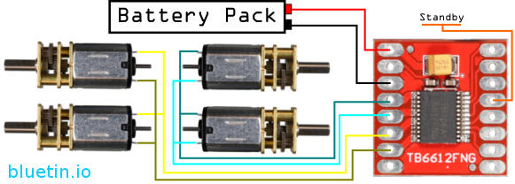
The TB6612FNG can support four medium power Micro Metal Gearmotors in a four-wheel drive robot vehicle design. However, use the stall current rating from DC motor specifications as a guide to match other DC motors with this motor driver.
You can enable the dc motors by connecting the motor driver standby pin to Vcc supply. Furthermore, if you are using a microcontroller with unpredictable pin states on bootup, you can use standby mode to ‘manually’ enable the motor driver following pin state initialisation.
TB6612FNG Arduino Connection
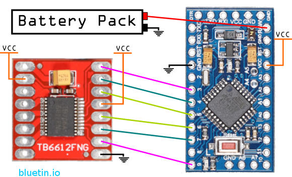
The Arduino compatible boards can connect directly to the motor driver. However, take note of the PWM connections, because these connections require specific Arduino pins to provide PWM.
The pins on the Arduino boards (ATMEGA) default to inputs. Therefore, you can tie the TB6612FNG driver standby pin to VCC. Arduino pins have to be configured as outputs to control the motor driver.
Arduino 3.3 Volt
The TB6612FNG motor driver can operate on 3.3 volts. Hence you can use the 3.3-volt version of the Arduino Pro Mini. A battery pack with either two 3.6 volt Li-Ion/Li-Po or six 1.2 volt NI-MH cells in series will work for this setup. You can reach full battery discharge and still have enough headroom for Arduino 3.3 volt regulator dropout voltage.
Arduino 5 Volt
With the battery pack configuration as above, there is going to be less headroom for the dropout voltage on the Arduino onboard 5 Volt regulator. So, depending on the type of onboard regulator, you may have to recharge the battery pack sooner to avoid affecting the 5-volt regulator output. Furthermore, when the batteries become weaker, the DC motors can cause significant voltage drops across the power supply. This voltage drop can cause the Arduino board to reset.
TB6612FNG and Arduino Power Supply
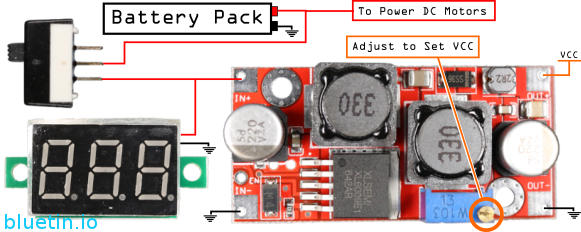
The above circuit will provide consistent VCC from battery packs of a wide voltage range. If you are using a mixture of 5 and 3.3 volts in a circuit, you will initially set the DC to DC buck-boost converter to 5 volts. Then, with 5 volts set, add a 3.3-volt regulator to it such as the AMS1117. So, with this, you can power the Arduino and TB6612FNG on 5-volts, and say an NRF24L01 wireless module on 3.3 volts.
BUCK-BOOST CONVERTER
This XL6009 buck-boost converter works with input voltages that are higher than, equal to, or lower than the regulated output voltage. Also known as a step-up, step-down converter, the XL6009 is the only module I could find on Ebay suitable for the application in this post. And while there are many step-down only DC to DC voltage converters available, the dropout voltage can be as much as 2 volts, which is too high for a 7.4-volt battery pack.
Pololu has DC to DC converters with better specifications than those you find on Ebay or Banggood. Check resources below for a link to their range of DC to DC converters.
BATTERY PACKS
While working with 6-volt rated DC motors, I will be expecting to work with 7.2 to 7.4-volt battery packs. For Arduino type robot applications, Ni-MH rechargeable batteries can be sufficient; where six cells will provide nominally 7.2 volts.
VOLTMETER
Adding an inexpensive mini digital voltmeter to the robot vehicle project can help keep track of the battery pack charge state on the fly. Keeping track of the battery pack charge state will be especially important when using Li-Ion or Li-Po batteries.
POWER OFF SWITCH
If using any DC to DC converter, some kind of battery isolation is necessary when the robot is not in use. Using a power off switch or disconnecting the battery pack will help avoid over-discharging batteries.
Tip: Arduino Serial Cable
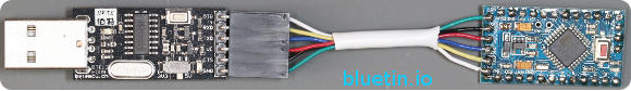
Soldering a custom serial cable to the Arduino Pro Mini Compatible will allow easier programming access. Here I chose green wire for ground connection at both ends, and this helps me to remember which way round to insert the serial module without seeing the Arduino board. The serial programming cable can be made to extend from the Arduino board to the outer shell of the project.
However, turn off or isolated the project power source before connecting the serial module to the Arduino board.
Tip: Prototyping PCB
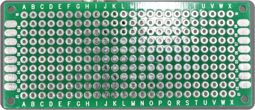
Soldering a collection of small components to a prototyping board will help keep the project tidy.
RESOURCES
TB6612FNG and Arduino Test Sketch
// Motor A, Left Side
const uint8_t pwmLeft = 9;      // ENA - Enable and PWM
const uint8_t leftForward = 7;  // IN1 - Forward Drive
const uint8_t leftReverse = 6;  // IN2 - Reverse Drive

// Motor B, Right Side
const uint8_t pwmRight = 3;     // ENB - Enable and PWM
const uint8_t rightForward = 5; // IN3 - Forward Drive
const uint8_t rightReverse = 4; // IN4 - Reverse Drive

//////////////// Start Functions //////////////////

// All Stop
void allStop() {
  digitalWrite(leftForward, LOW);
  digitalWrite(leftReverse, LOW);
  digitalWrite(rightForward, LOW);
  digitalWrite(rightReverse, LOW);
  analogWrite(pwmLeft, 0);
  analogWrite(pwmRight, 0);
}

void allForward() {
  digitalWrite(leftForward, HIGH);
  digitalWrite(leftReverse, LOW);
  digitalWrite(rightForward, HIGH);
  digitalWrite(rightReverse, LOW);
  analogWrite(pwmLeft, 255);
  analogWrite(pwmRight, 255);
}

void allReverse() {
  digitalWrite(leftForward, LOW);
  digitalWrite(leftReverse, HIGH);
  digitalWrite(rightForward, LOW);
  digitalWrite(rightReverse, HIGH);
  analogWrite(pwmLeft, 255);
  analogWrite(pwmRight, 255);
}

void skidsteerLeft() {
  digitalWrite(leftForward, LOW);
  digitalWrite(leftReverse, HIGH);
  digitalWrite(rightForward, HIGH);
  digitalWrite(rightReverse, LOW);
  analogWrite(pwmLeft, 255);
  analogWrite(pwmRight, 255);
}

void skidsteerRight() {
  digitalWrite(leftForward, HIGH);
  digitalWrite(leftReverse, LOW);
  digitalWrite(rightForward, LOW);
  digitalWrite(rightReverse, HIGH);
  analogWrite(pwmLeft, 255);
  analogWrite(pwmRight, 255);
}

//////////////// End Functions //////////////////

void setup() {
  // Set pins to motor driver (TB6612FNG) to outputs
  pinMode(pwmLeft, OUTPUT);
  pinMode(leftForward, OUTPUT);
  pinMode(leftReverse, OUTPUT);
  pinMode(pwmRight, OUTPUT);
  pinMode(rightForward, OUTPUT);
  pinMode(rightReverse, OUTPUT);
}

void loop() {
  allStop();  // Stop all dc motors
  delay(1000);
  allForward(); // Drive dc motors forward
  delay(2000);
  allReverse(); // Drive dc motors in reverse
  delay(2000);
  skidsteerLeft();  // Skidsteer spin left direction
  delay(2000);
  skidsteerRight(); // Skidsteer spin right direction
  delay(2000);
}
Related Articles

GPIO PWM For Raspberry Pi H-Bridge DC Motor Control – Link.
L298N H-Bridge DC Motor Driver Module Quick Start Guide – Link.
Buying Featured Items
The purchase price is going to vary greatly depending on how quickly you want the items. Therefore shop around checking out Amazon, Ebay, Adafruit and local electronic stores.
DISCLAIMER: This feature may contain affiliate links, which means that if you click on one of the product links, I’ll receive a small commission. This helps support the website and allows me to continue to make features like this. Thank you for the support!
BANGGOOD
- DC-DC Boost Buck Adjustable Step Up Step Down Converter XL6009 Module – Link.
- TB6612FNG Dual DC Motor Driver Module – Link.
- 0.28 Inch 2.5V-30V Mini Digital Volt Meter – Link.
- Arduino compatible Pro Mini 5 volts – Link.
- PCB Panel Mini Vertical Slide Switch – Link.
- 40pcs FR-4 2.54mm Double Sided Prototype PCB – Link.
On Closing
I hope you find this article useful – TB6612FNG Dual DC Motor Driver and Arduino Circuit guide – Guide, please like and share.
2 thoughts on “TB6612FNG Dual DC Motor Driver and Arduino Circuit guide”
Comments are closed.