In this feature, I take another look at the TB6612FNG motor driver, but this time, with the Raspberry Pi instead of the Arduino. The H-Bridge module is the chosen robot driver for my Pi Wars entry effort. View this post for circuit examples and Python test code to get started with your own Robot Project.
The Micro Metal Gear Motors are ideal for lightweight robot projects and to drive them, the TB6612FNG is a perfect fit. Unlike the L298N H-Bridge module, the TB6612FNG logic can take power from the Raspberry Pi 3.3-Volt Supply. To learn more about this module in more detail, also view the following post after this one.
TB6612FNG Dual DC Motor Driver and Arduino Circuit guide – Link.
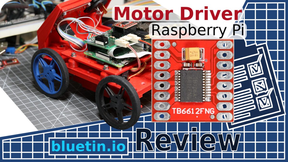
TB6612FNG Motor Driver
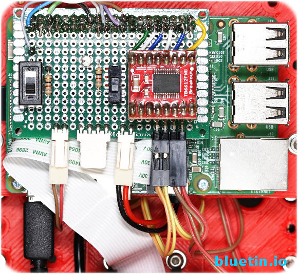
The above image shows my current motor driver setup for my Pi Wars robot entry. It is so far working very well, and the Micro DC Metal Gear Motors appear to be a perfect match for the TB6612FNG. I’m using a Raspberry Pi 3 in this case because I am using camera vision applications with OpenCV libraries. OpenCV works best with multicore processors, especially when attempting to do other IO tasks at the same time. However, for robot control without real-time camera vision, any Raspberry Pi will do.
The compact size of the TB6612FNG Dual H-Bridge Driver allows it to be put on to a small prototyping board. This arrangement then provides space for adding connectors for DC motors and power. To avoid accidental sabotage to the Raspberry Pi, I chose different connector styles to prevent reverse polarity and wrong connections. You can solder wires directly to the prototyping board but use connecting wires of good quality for this purpose. Connectors make the components more modular and are ideal when swapping such things as DC motors or other attachments.
TB6612FNG Motor Driver Circuit
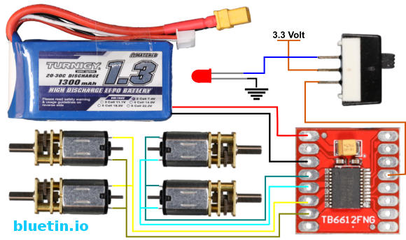
Note – Add a suitable resistor for the LED if building the circuit above.
So, here we look at the DC Motor side of things where we have the motor driver module connecting to the DC Motors. I also include a slide switch in the circuit to enable or disable the H-Bridge Module. Due to the nature of the Raspberry Pi Pins, the DC motors may spin up at system bootup. The state of the Raspberry PI GPIO pins may be random on bootup, so a method to disable the driver module is necessary.
To avoid the Rasberry Pi operating the Dual H-Bridge driver without GPIO code, a method to disable the H-Bridge is necessary. Connecting a switch to the TB6612FNG enable pin will provide manual control of the driver operation state. Therefore, once you run Python code to initialise the GPIO pins, it is safe to switch on the H-Bridge module. Attaching an LED to the switch will show the H-Bridge is off when the LED light is on. Therefore, if the robot is ready for operation, use the switch to enable the H-Bridge module, and the LED will switch off in the process.
The DC motors are run directly off the battery, which in this case, is a two cell Li-Po pack. This battery works fine for the motors I currently use which are medium power 6V Micro Metal Gear Motors. I find that while driving four DC motors, they start to lose power at about 6.5V of remaining battery level. So while running a Raspberry Pi as well, it is best not to let the battery become too weak before recharging. Causing the Raspberry Pi to lose power may corrupt the OS SD Card.
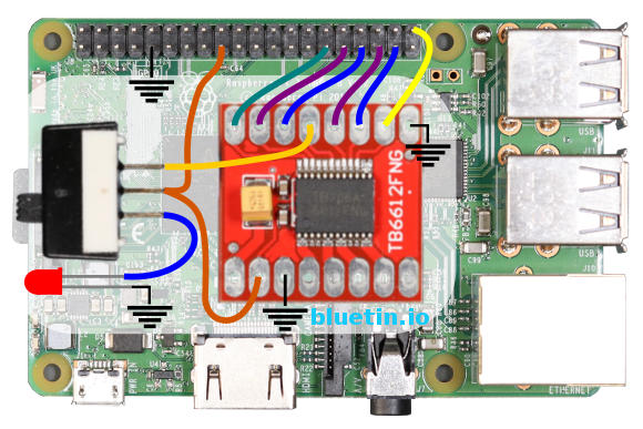
Raspberry Pi and Motor Driver Connection
Note – Add a suitable resistor for the LED if building the circuit above.
The motor driver ‘Enable’ switch also appears in this circuit to show supply connection from the Raspberry Pi. The Raspberry Pi also supplies 3.3V to the H-Bridge driver module. IO connections between the driver module and the GPIO Pins are flexible. This flexibility is because PWM can be output from most GPIO pins. The GPIO pins I use in this circuit are convenient for my application.
However, when selecting GPIO pins to drive the H-Bridge module, it is best to avoid the serial pins just in case you need them later.
BUCK-BOOST CONVERTER
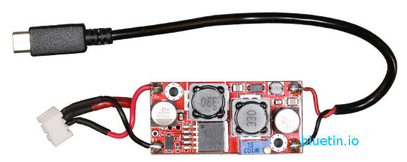
This XL6009 buck-boost converter works with input voltages that are higher than, equal to, or lower than the regulated output voltage. Also known as a step-up, step-down converter, the XL6009 is the only module I can find on Ebay suitable for the application in this post. And while there are many step-down-only DC to DC voltage converters available, the dropout voltage can be as much as 2 volts, which is too high for a nominal 7.4-volt battery pack.
However, the XL6009 DC to DC converter can power the Raspberry Pi 3 reliably given my experience. The module sits between the battery and the Raspberry Pi. So, to connect the driver module to the Raspberry Pi, a USB cable is cut to length leaving the micro USB connector on one end to provide power to the Pi board. Then the cut end is stript and then soldered to the output of the XL6009 module. Soldering a JST-XH type connector to the XL6009 will allow connection to the battery balance charge lead.
Remember to adjust the POT on the XL6009 to 5V before connecting to the Raspberry Pi.
MOTOR DRIVER FEATURE LAST WORDS

If you are looking to solder components to a prototyping PCB, the wiring can quickly get complicated. I often use specific colours for different connection types to try and keep track. For instance, I use black for ground, orange for 3.3V, red for 5V and other wire colours for data lines. Furthermore, you may also require a mixture of solid core and stranded wire.
The motor driver circuit is still a work in progress, and it should evolve quite a bit more before I’m satisfied with it. While there are excellent H-Bridge solutions around for the Raspberry Pi, building my own adds a bit more satisfaction level to the project.
Motor Driver Six Wire H-Bridge Python Code Example
"""

File: skidsteer_two_pwm_test.py

This code will test Raspberry Pi GPIO PWM on four GPIO
pins. The code test ran with L298N H-Bridge driver module connected.

Website:	www.bluetin.io
Date:		27/11/2017
"""

__author__ = "Mark Heywood"
__version__ = "0.1.0"
__license__ = "MIT"

from gpiozero import PWMOutputDevice
from gpiozero import DigitalOutputDevice
from time import sleep

#///////////////// Define Motor Driver GPIO Pins /////////////////
# Motor A, Left Side GPIO CONSTANTS
PWM_DRIVE_LEFT = 21		# ENA - H-Bridge enable pin
FORWARD_LEFT_PIN = 26	# IN1 - Forward Drive
REVERSE_LEFT_PIN = 19	# IN2 - Reverse Drive
# Motor B, Right Side GPIO CONSTANTS
PWM_DRIVE_RIGHT = 5		# ENB - H-Bridge enable pin
FORWARD_RIGHT_PIN = 13	# IN1 - Forward Drive
REVERSE_RIGHT_PIN = 6	# IN2 - Reverse Drive

# Initialise objects for H-Bridge GPIO PWM pins
# Set initial duty cycle to 0 and frequency to 1000
driveLeft = PWMOutputDevice(PWM_DRIVE_LEFT, True, 0, 1000)
driveRight = PWMOutputDevice(PWM_DRIVE_RIGHT, True, 0, 1000)

# Initialise objects for H-Bridge digital GPIO pins
forwardLeft = DigitalOutputDevice(FORWARD_LEFT_PIN)
reverseLeft = DigitalOutputDevice(REVERSE_LEFT_PIN)
forwardRight = DigitalOutputDevice(FORWARD_RIGHT_PIN)
reverseRight = DigitalOutputDevice(REVERSE_RIGHT_PIN)

def allStop():
	forwardLeft.value = False
	reverseLeft.value = False
	forwardRight.value = False
	reverseRight.value = False
	driveLeft.value = 0
	driveRight.value = 0

def forwardDrive():
	forwardLeft.value = True
	reverseLeft.value = False
	forwardRight.value = True
	reverseRight.value = False
	driveLeft.value = 1.0
	driveRight.value = 1.0

def reverseDrive():
	forwardLeft.value = False
	reverseLeft.value = True
	forwardRight.value = False
	reverseRight.value = True
	driveLeft.value = 1.0
	driveRight.value = 1.0

def spinLeft():
	forwardLeft.value = False
	reverseLeft.value = True
	forwardRight.value = True
	reverseRight.value = False
	driveLeft.value = 1.0
	driveRight.value = 1.0

def SpinRight():
	forwardLeft.value = True
	reverseLeft.value = False
	forwardRight.value = False
	reverseRight.value = True
	driveLeft.value = 1.0
	driveRight.value = 1.0

def forwardTurnLeft():
	forwardLeft.value = True
	reverseLeft.value = False
	forwardRight.value = True
	reverseRight.value = False
	driveLeft.value = 0.2
	driveRight.value = 0.8

def forwardTurnRight():
	forwardLeft.value = True
	reverseLeft.value = False
	forwardRight.value = True
	reverseRight.value = False
	driveLeft.value = 0.8
	driveRight.value = 0.2

def reverseTurnLeft():
	forwardLeft.value = False
	reverseLeft.value = True
	forwardRight.value = False
	reverseRight.value = True
	driveLeft.value = 0.2
	driveRight.value = 0.8

def reverseTurnRight():
	forwardLeft.value = False
	reverseLeft.value = True
	forwardRight.value = False
	reverseRight.value = True
	driveLeft.value = 0.8
	driveRight.value = 0.2

def main():
	allStop()
	forwardDrive()
	sleep(5)
	reverseDrive()
	sleep(5)
	spinLeft()
	sleep(5)
	SpinRight()
	sleep(5)
	forwardTurnLeft()
	sleep(5)
	forwardTurnRight()
	sleep(5)
	reverseTurnLeft()
	sleep(5)
	reverseTurnRight()
	sleep(5)
	allStop()


if __name__ == "__main__":
    """ This is executed when run from the command line """
    main()
Related Articles

GPIO PWM For Raspberry Pi H-Bridge DC Motor Control – Link.
TB6612FNG Dual DC Motor Driver and Arduino Circuit guide – Link.
Buying Featured Items
The purchase price is going to vary greatly depending on how quickly you want the items. Therefore shop around checking out Amazon, Ebay, Adafruit and local electronic stores.
DISCLAIMER: This feature may contain affiliate links, which means that if you click on one of the product links, I’ll receive a small commission. This commission helps support the website and allows me to continue to make features like this. Thank you for the support!
BANGGOOD
- DC-DC Boost Buck Adjustable Step Up Step Down Converter XL6009 Module – Link.
- TB6612FNG Dual DC Motor Driver Module – Link.
- 0.28 Inch 2.5V-30V Mini Digital Volt Meter – Link.
- PCB Panel Mini Vertical Slide Switch – Link.
- 40pcs FR-4 2.54mm Double Sided Prototype PCB – Link.
UK Searches:
UK Amazon:
- Raspberry Pi – Search.
- MicroSD Card – Search.
- Raspberry Pi Compatible Wi-Fi Dongle – Search.
- Raspberry Pi Camera – Search.
US Searches:
US Amazon:
- Raspberry Pi – Search.
- MicroSD Card – Search.
- Raspberry Pi Compatible Wi-Fi Dongle – Search.
- Raspberry Pi Camera – Search.
On Closing
I hope you find this article useful – Motor Driver for Raspberry Pi Robot using TB6612FNG, please like and share.
2 thoughts on “Motor Driver for Raspberry Pi Robot using TB6612FNG”
Comments are closed.