
This reference or guide should provide a quick route to setting up the NRF24L01 wireless module. Thus Arduino code is included for send and receive test.
I never seem to remember how to hook-up the NRF24L01 2.4GHz radio without searching the internet for instruction guides. Therefore I decided to write a quick reference or guide to get me started quickly.
So I’m interested in the NRF24L01 transceiver module primarily for controlling robots over wireless. My earlier experience with the wireless module has been good and has performed well with the robots I’ve built so far. Furthermore, I like the data packet handling feature the module comes with which simplifies the Arduino code.
NRF24L01 transceiver module Overview
Short Specification For Featured Item
- On air data rates up to 2Mbps.
- Ultra low power operation with on chip voltage regulator.
- 11.3mA TX at 0dBm output power.
- 13.5mA RX at 2Mbps air data rate.
- 1.9 to 3.6 supply voltage range.
- Also 5v tolerant inputs.
- Built-in 2.4Ghz antenna.
- Automatic payload checks.
- Built-in hardware CRC error detection.
- Can be directly connected to a variety of micro-controllers.
- Size: 28.8mm X 15.4mm X 13mm with PCB header pins.
- Size: 28.8mm X 15.4mm X 5mm without PCB header pins.
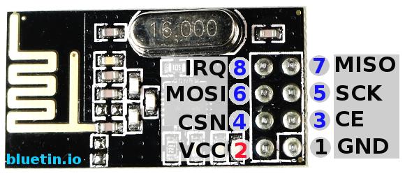
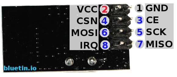
NRF24L01 Pinout Diagram
Module pinouts front and back.
Wireless Module Set-up
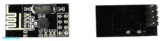
While there are a few different module sizes and configurations I generally stick to the module as shown above. As a standard practice I power this module with a separate 3.3 volt regulator – especially when using 3.3 volt micro-controllers.
Since I’ll be using the NRF24L01 module in robots I’ll want the module to be as compact as possible. Therefore I’ll be removing the PCB header pins and then solder wires directly on to the module pads, like in the image below.
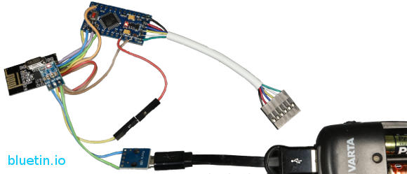
I use mostly Arduino Pro Mini compatible due to it’s small compact size. They are also very cheap and can be bought by the handfuls from Ebay. And like the wireless module, wires are soldered directly on to the micro-controller pads.
Arduino Libraries
These days I’ve found it more convenient to unzip the libraries in to the Windows: Documents/Arduino/libraries directory. So find below a link to download the library. Thus remember to remove any existing NRF24L01 libraries already installed.
Download the NRF24L01 library here.
Arduino and NRF24L01 pinout diagram
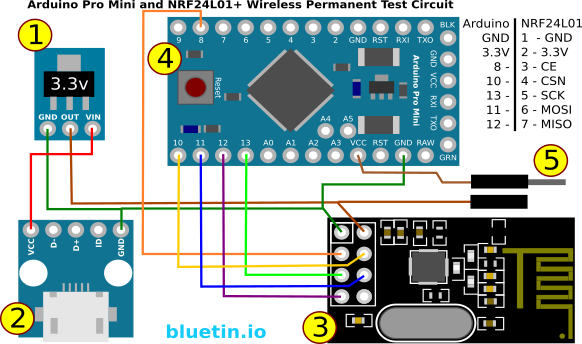
Above is a diagram of a test circuit I use. I use this circuit to test new wireless module set-ups for debugging.
- I use regulators that are known to provide good wireless module stability. The AMS1117-3.3 module is working well enough for me so far.
- For convenience of powering the test circuit I’ve added a USB Micro B breakout.
- The NRF24L01 wireless transceiver module. This module must have a 3.3 volt supply. However the input pins are 5 volt tolerant.
- Arduino Pro Mini in this case is the 3.3 volt version. The 5 volt version will work just the same but it will need a separate power source supplying 5 volts. Thus the GNDs will still need to remain common.
- A jumper pin is fitted to allow separation of the Arduino Pro from the circuit’s power source. So whenever you connect the circuit to the computer the jumper pin is separated. Hence this allows the wireless module to continue to operate from the AMS1117 module while the Arduino draws power from the computer. Of course you will still need to supply the AMS1117 from another power source.
The Test Code
The following bits of code can be used to initially test your NRF24L01 module in a new circuit. Hence one piece of code is for sending data while the other receives data. Furthermore the receiving data has a counter to make it easy to check for dropped packets when testing the wireless transceiver at different ranges.
The sending code For Arduino
// SimpleTx - the master or the transmitter

#include <SPI.h>
#include <nRF24L01.h>
#include <RF24.h>


#define CE_PIN   8
#define CSN_PIN 10

const byte slaveAddress[5] = {'R','x','A','A','A'};


RF24 radio(CE_PIN, CSN_PIN); // Create a Radio

char dataToSend[10] = "Message 0";
char txNum = '0';


unsigned long currentMillis;
unsigned long prevMillis;
unsigned long txIntervalMillis = 1000; // send once per second

//====================

void send() {

    bool rslt;
    rslt = radio.write( &dataToSend, sizeof(dataToSend) );
        // Always use sizeof() as it gives the size as the number of bytes.
        // For example if dataToSend was an int sizeof() would correctly return 2

    Serial.print("Data Sent ");
    Serial.print(dataToSend);
    if (rslt) {
        Serial.println("  Acknowledge received");
        updateMessage();
    }
    else {
        Serial.println("  Tx failed");
    }
}

//================

void updateMessage() {
        // so you can see that new data is being sent
    txNum += 1;
    if (txNum > '255') {
        txNum = '0';
    }
    dataToSend[8] = txNum;
}

void setup() {

    Serial.begin(9600);

    Serial.println("SimpleTx Starting");

    radio.begin();
    radio.setDataRate( RF24_250KBPS );
    radio.setRetries(3,5); // delay, count
    radio.openWritingPipe(slaveAddress);
}

//====================

void loop() {
    currentMillis = millis();
    if (currentMillis - prevMillis >= txIntervalMillis) {
        send();
        prevMillis = millis();
    }
}
The Receiving Code For Arduino
#include <SPI.h>
#include <nRF24L01.h>
#include <RF24.h>

#define CE_PIN   8
#define CSN_PIN 10

const byte thisSlaveAddress[5] = {'R','x','A','A','A'};

RF24 radio(CE_PIN, CSN_PIN);

char dataReceived[10]; // this must match dataToSend in the TX
bool newData = false;

//==============

void getData() {
    if ( radio.available() ) {
        radio.read( &dataReceived, sizeof(dataReceived) );
        newData = true;
    }
}

void showData() {
    if (newData == true) {
        Serial.print("Data received ");
        Serial.print(dataReceived);
        Serial.print(" - Counter  ");
        int counter = dataReceived[8];
        Serial.println(counter);
        newData = false;
    }
}

//===========

void setup() {

    Serial.begin(9600);

    Serial.println("SimpleRx Starting");
    radio.begin();
    radio.setDataRate( RF24_250KBPS );
    radio.openReadingPipe(1, thisSlaveAddress);
    radio.startListening();
}

//=============

void loop() {
    getData();
    showData();
}
Other resources
More detailed information can be found here.
Buying Featured Items
The purchase price is going to vary greatly depending on how quickly you want the items. Therefore shop around checking out Amazon, Ebay and local electronic stores.
Also check the last article for searching related featured items – article link below.
UK Searches:
UK Amazon
US Searches:
US Amazon
On Closing
I hope you found this article useful – NRF24L01 2.4GHz Transceiver Quick Reference, please like and share.